A Formal Introduction to Boolean Expressions
So far we have learned the basic gates. Now we need to learn how to use them wisely. A Boolean expression can often be written in a shorter form, and a shorter expression means a circuit with fewer gates, fewer wires, lower cost, and faster speed. But first…
What really is a Boolean expression?
A Boolean expression is a short statement that tells us how an output depends on its inputs. It is made of three things:
- Variables: letters like A, B and C. Each variable can only be 0 or 1.
- Operations: the gates we have learned. AND, OR and NOT.
- Constants: the fixed values 0 and 1.
Here are the symbols we use:
| Operation | Symbol | Example | Read as |
|---|---|---|---|
| AND | · (or no symbol) |
A · B or AB | A AND B |
| OR | + |
A + B | A OR B |
| NOT | ' |
A’ | NOT A |
Some examples of Boolean expressions:
Y = A + B
F = A·B + C'
F = (A + B)·C
The result of a Boolean expression is always 0 or 1.
Evaluating an expression
To find the output, we put in the values of the inputs and work it out step by step. The order is:
- Brackets first
- Then NOT
- Then AND
- Then OR
Example: find F = A·B + C’ when A = 1, B = 0 and C = 0.
- A·B = 1 · 0 = 0
- C’ = 0’ = 1
- F = 0 + 1 = 1
Always remember that an expression is actually a circuit. Every Boolean expression can be drawn as a circuit. Each variable is an input wire, and each operation is a gate. For F = A·B + C’ we need:
- 1 AND gate for A·B
- 1 NOT gate for C’
- 1 OR gate to combine them as indicated by the + sign.
So the more operations an expression has, the more gates the circuit needs. That is why a shorter expression gives a cheaper circuit and we always want that hence we need its simplification of expressions.
It may sound intimidating at first, but lets try to understand this using an example to understand it in a better way. So consider we have the boolean expression:
F(x,y,z) = x + y'z
first lets draw a truth table for it. Keep in mind we have three variables here which are x, y and z so we will need three columns for them in the truth table:
| x | y | z | | — | — | — |
Since they are 3, so we will have total 8 possible combinations for them as 2^3 is 8:
| x | y | z |
|---|---|---|
| 0 | 0 | 0 |
| 0 | 0 | 1 |
| 0 | 1 | 0 |
| 0 | 1 | 1 |
| 1 | 0 | 0 |
| 1 | 0 | 1 |
| 1 | 1 | 0 |
| 1 | 1 | 1 |
Now lets focus on our expression.. So it is x + y'z, to make things simpler for us, we will separate the expression in 2 parts, first lets make a separate column for y' :
| x | y | z | y’ |
|---|---|---|---|
| 0 | 0 | 0 | 1 |
| 0 | 0 | 1 | 1 |
| 0 | 1 | 0 | 0 |
| 0 | 1 | 1 | 0 |
| 1 | 0 | 0 | 1 |
| 1 | 0 | 1 | 1 |
| 1 | 1 | 0 | 0 |
| 1 | 1 | 1 | 0 |
y' simply means invert y. Now lets evaluate the second part of the expression that is x+y'z:
| x | y | z | y’ | y’.z |
|---|---|---|---|---|
| 0 | 0 | 0 | 1 | 0 |
| 0 | 0 | 1 | 1 | 1 |
| 0 | 1 | 0 | 0 | 0 |
| 0 | 1 | 1 | 0 | 0 |
| 1 | 0 | 0 | 1 | 0 |
| 1 | 0 | 1 | 1 | 1 |
| 1 | 1 | 0 | 0 | 0 |
| 1 | 1 | 1 | 0 | 0 |
And now lets take the whole expression (x + y’z):
| x | y | z | y’ | y’.z | x+ y’z |
|---|---|---|---|---|---|
| 0 | 0 | 0 | 1 | 0 | 0 |
| 0 | 0 | 1 | 1 | 1 | 1 |
| 0 | 1 | 0 | 0 | 0 | 0 |
| 0 | 1 | 1 | 0 | 0 | 0 |
| 1 | 0 | 0 | 1 | 0 | 1 |
| 1 | 0 | 1 | 1 | 1 | 1 |
| 1 | 1 | 0 | 0 | 0 | 1 |
| 1 | 1 | 1 | 0 | 0 | 1 |
Now we have the truth table ready, and lets translate the boolean expression into a circuit and then confirm whether our circuit conforms with the truth table that is created or not, so the truth table here is a way to check whether our circuit behaves correctly or not…
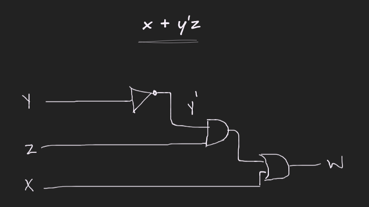
So for this boolean expression we are going to use a NOT gate as we have y', then we will use an AND gate as we have y'z, and since x and y'z are getting added so for that we will need an OR gate. The circuit diagram should look something like:
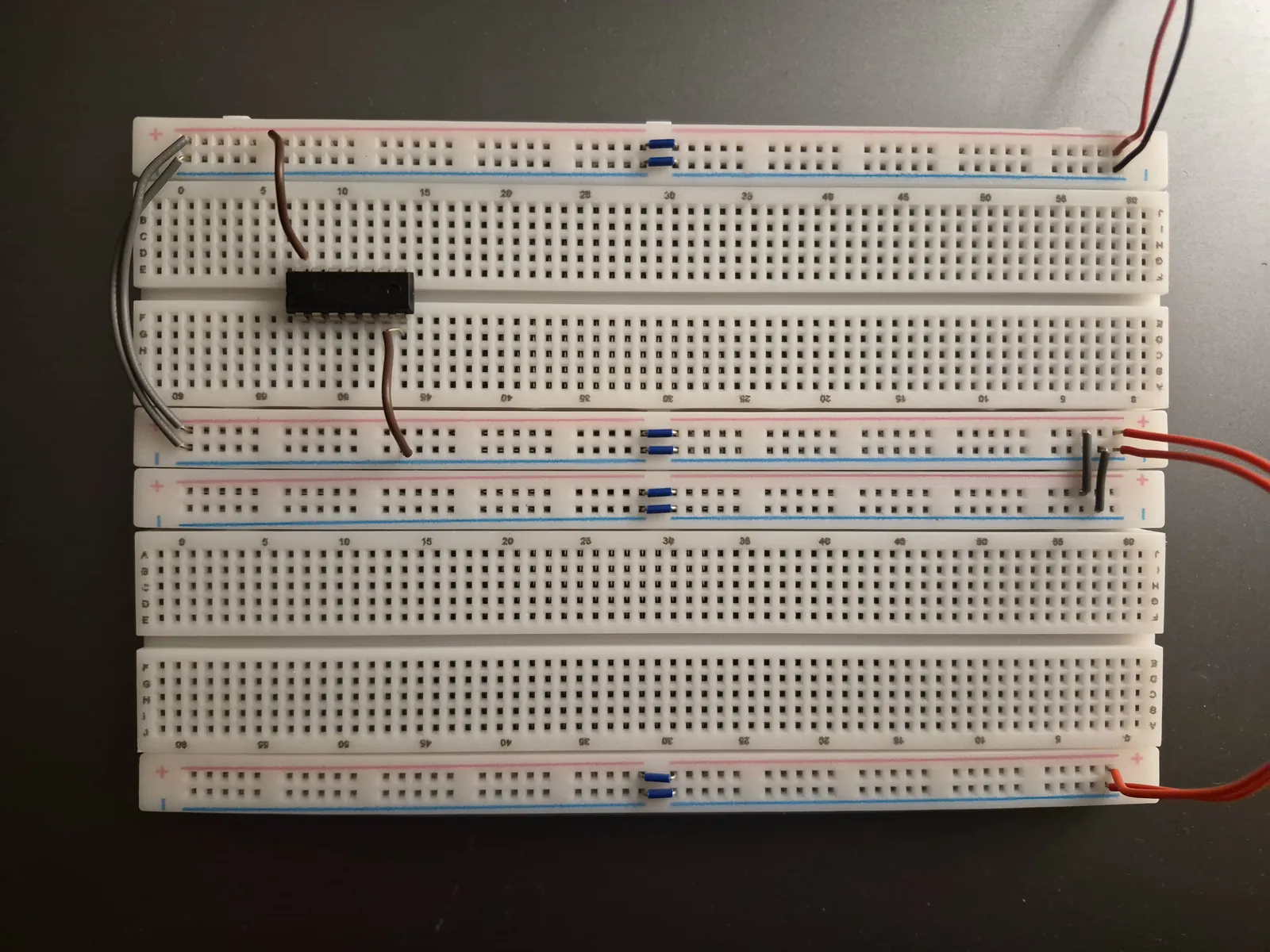
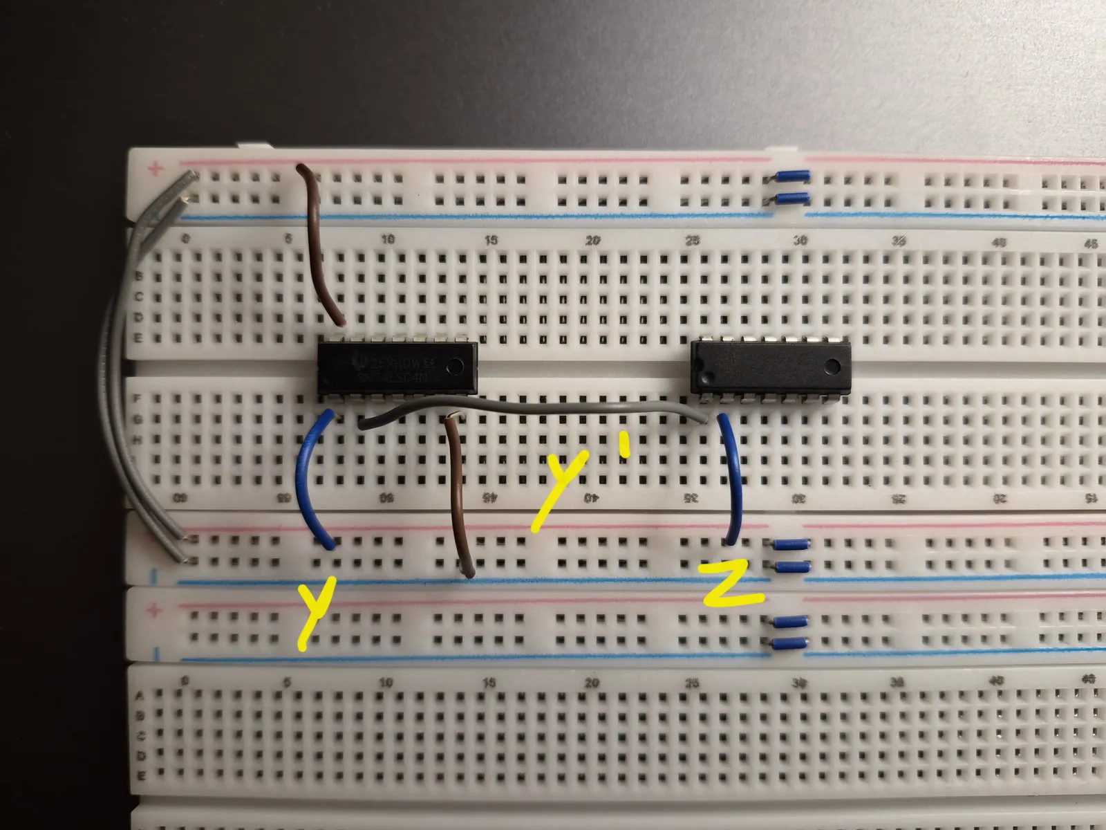
Lets delve into some practical work to get a better idea. First of all I got the 7404 IC which is our NOT gate to invert our y input:
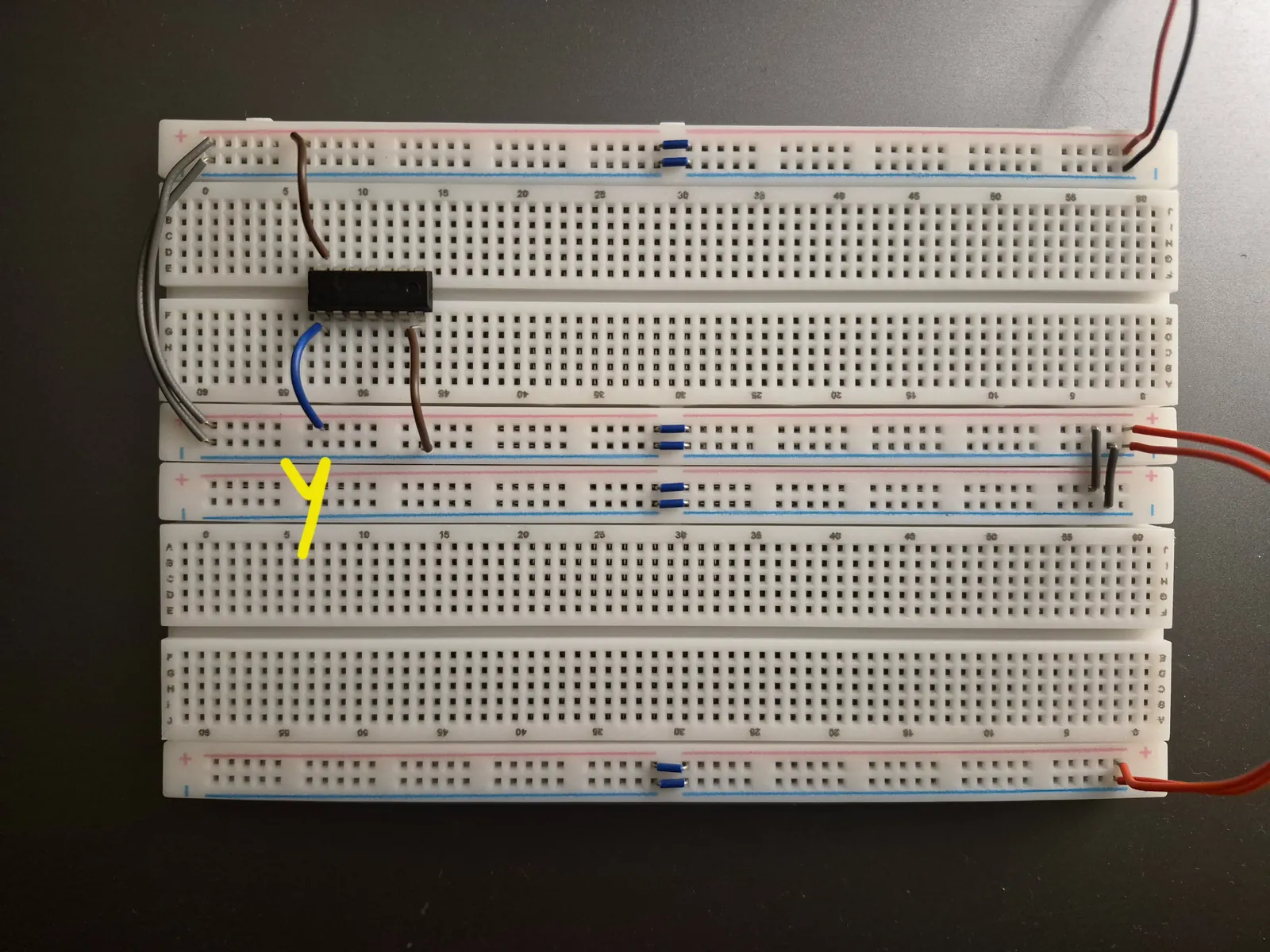
Next we are going to get our input wire y in the first logic circuit (all input wires x, y and z use the blue jumper wire).
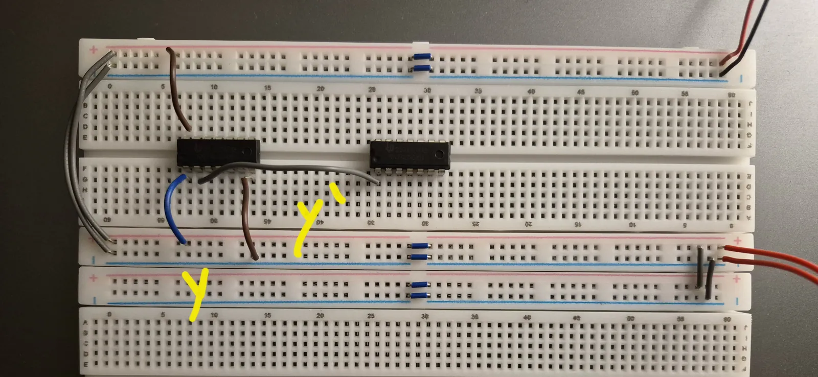
Next we are going to insert our 7408 IC which is our AND gate, and get the output of NOT gate which is y' as an input to our AND gate:
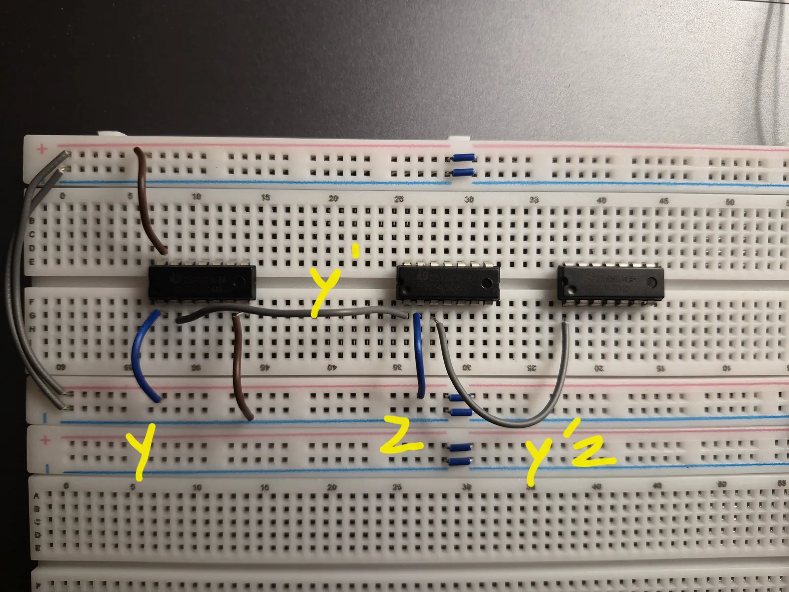
Once we have y' as an input to AND gate, we are going to get the input wire 2 which is Z:
We will then get our 7432 IC which is the OR gate and get the output of the AND gate which is y'z to it as the first input:
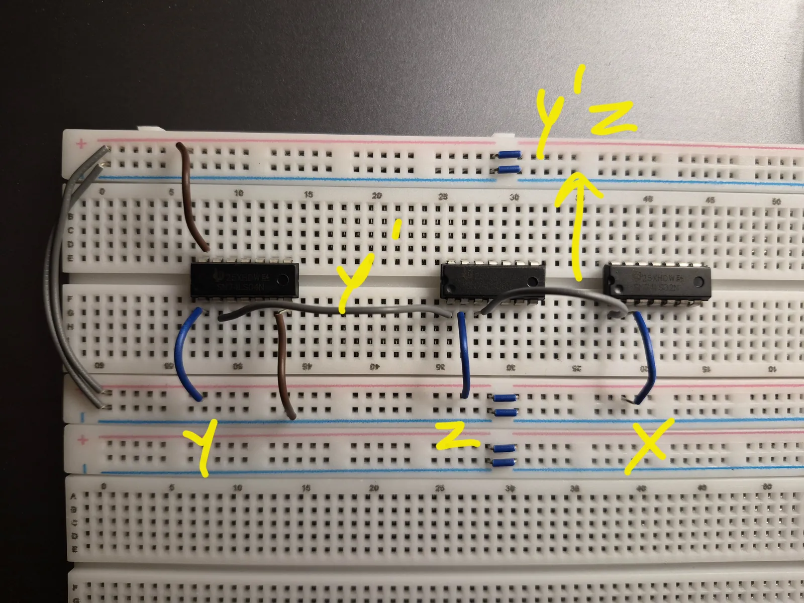
Get the input wire x in OR gate:
Once all the input wires y, z and x are HIGH, the LED lights up!
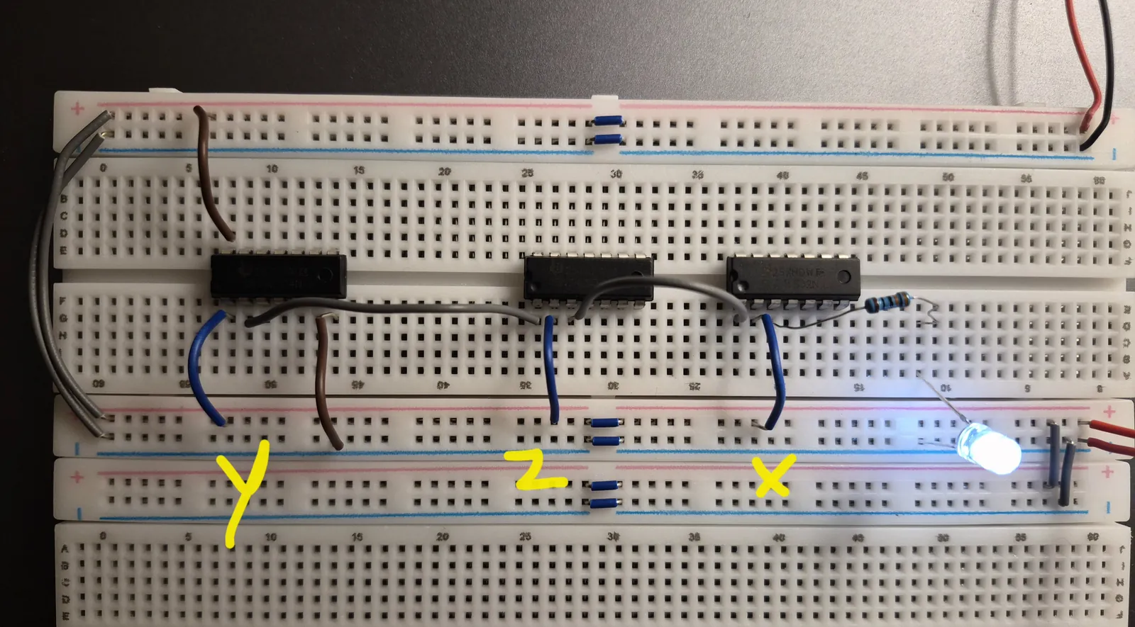
Lets confirm our results from the truth table:
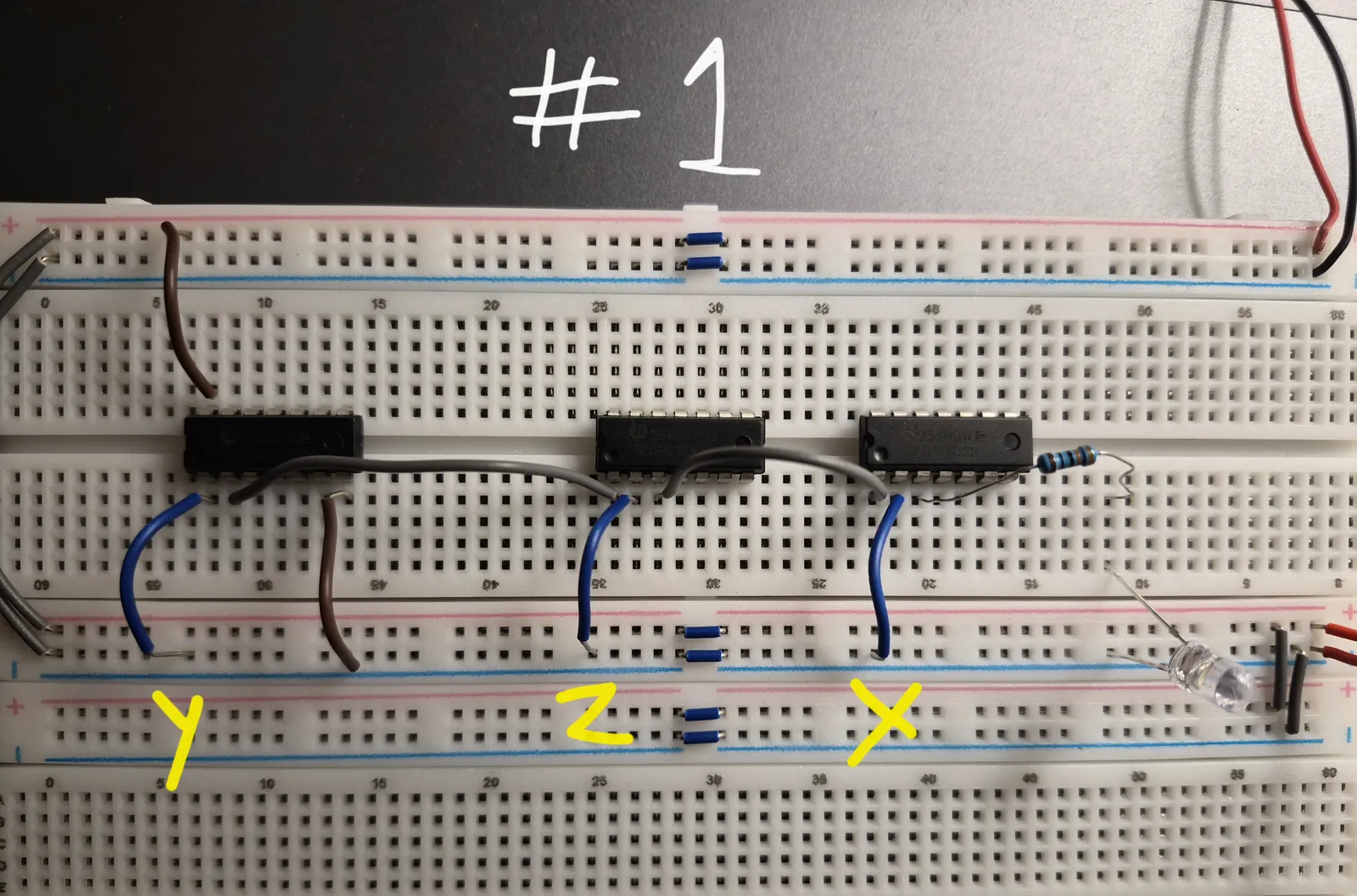
Case 1:
This is the first row of our truth table:
| x | y | z | y’ | y’.z | x+ y’z |
|---|---|---|---|---|---|
| 0 | 0 | 0 | 1 | 0 | 0 |
All three input wires are LOW and none is HIGH so the LED doesn’t light up as x+y'z is 0.
Case 2:
| x | y | z | y’ | y’.z | x+ y’z |
|---|---|---|---|---|---|
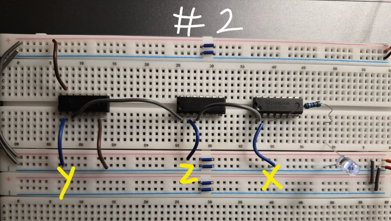
| 0 | 0 | 1 | 1 | 1 | 1 |
When x and y inputs are LOW, and z is HIGH, our bulb lights up as the result of x+y'z is 1.
Case 3:
| x | y | z | y’ | y’.z | x+ y’z |
|---|---|---|---|---|---|
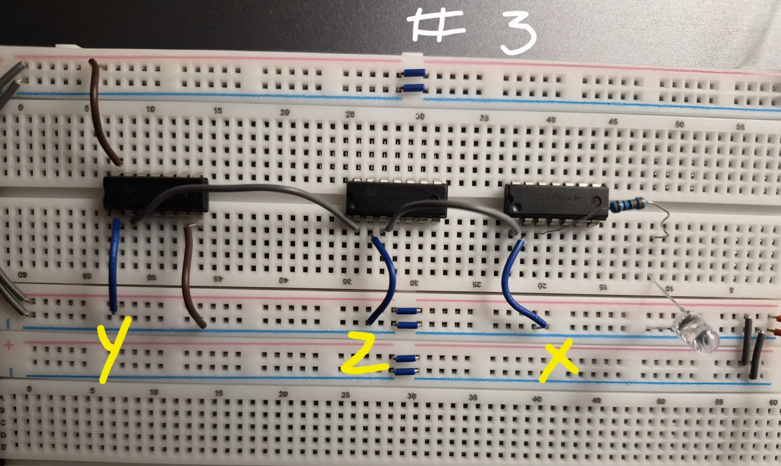
| 0 | 1 | 0 | 0 | 0 | 0 |
When input wires x and z are LOW, and y is HIGH, LED does not light up as x+y'z is 0:
Case 4:
| x | y | z | y’ | y’.z | x+ y’z |
|---|---|---|---|---|---|
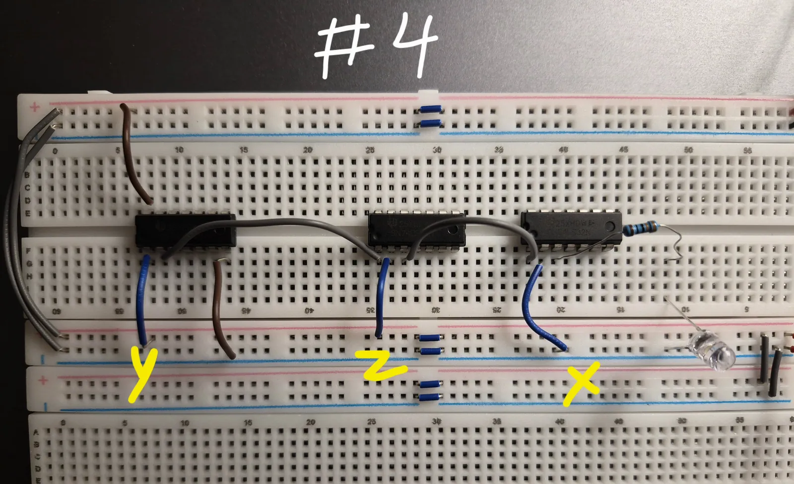
| 0 | 1 | 1 | 0 | 0 | 0 |
When input wire x is LOW but y and z are HIGH, the LED doesn’t light up again as x+y'z is 0:
Case 5:
| x | y | z | y’ | y’.z | x+ y’z |
|---|---|---|---|---|---|
| 1 | 0 | 0 | 1 | 0 | 1 |
When x is HIGH and y and z are LOW, our LED lights up as x+y'z is 1:
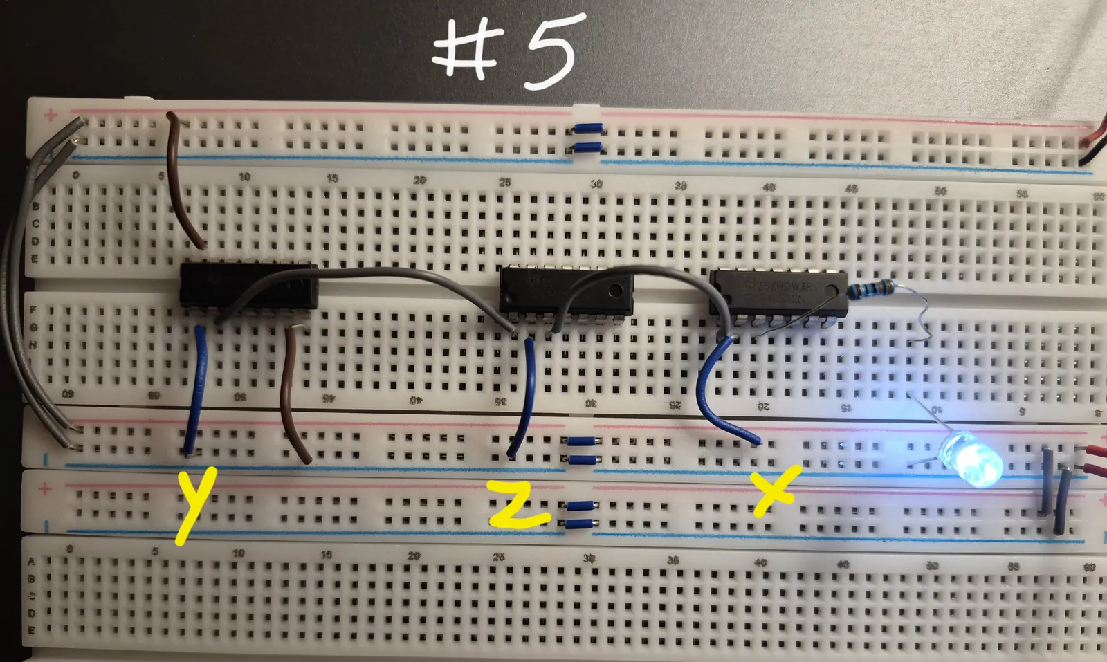
Case 6:
| x | y | z | y’ | y’.z | x+ y’z |
|---|---|---|---|---|---|
| 1 | 0 | 1 | 1 | 1 | 1 |
When x is HIGH, and if z is HIGH but y is LOW, we again get the LED lit as the result of x+y'z is 1:
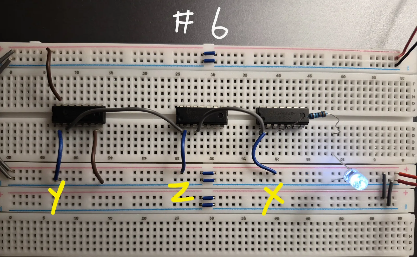
Case 7:
| x | y | z | y’ | y’.z | x+ y’z |
|---|---|---|---|---|---|
| 1 | 1 | 0 | 0 | 0 | 1 |
Again our LED lights up as x is HIGH:
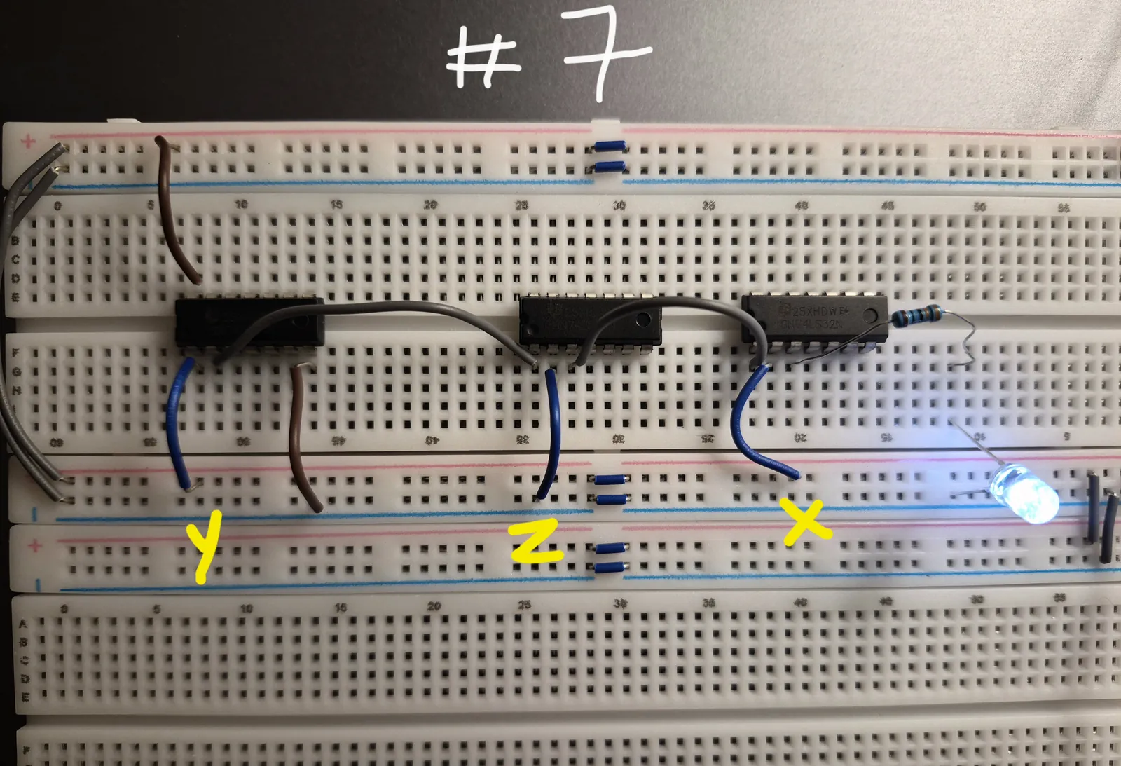
Case 8:
| x | y | z | y’ | y’.z | x+ y’z |
|---|---|---|---|---|---|
| 1 | 1 | 1 | 0 | 0 | 1 |
In the final case when every input is HIGH our LED lights up again as the result of the boolean expression is 1!
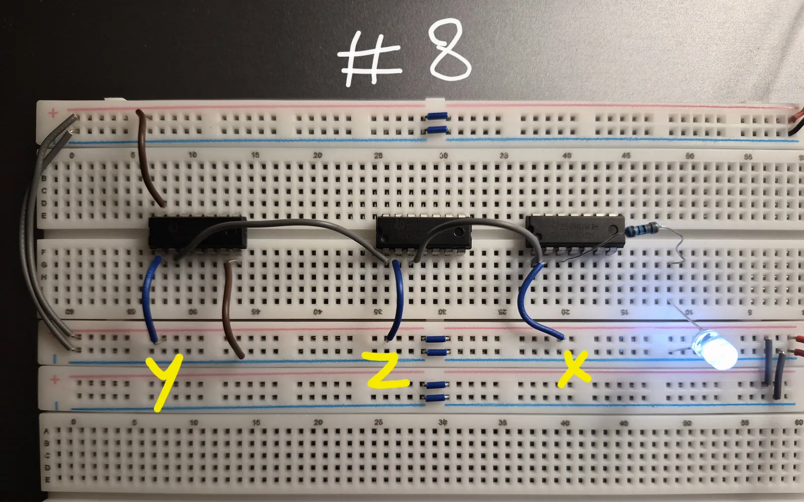
So in this practical we took a Boolean expression, F = x + y'z, and worked with it in three ways. First as an expression, as a truth table, and as a real circuit on the breadboard. We first filled in the truth table step by step, finding y', then y'z, then the whole expression. Then we built the circuit using NOT, AND and OR gates and tested every input combination.
The LED matched the truth table in every row. This shows that a Boolean expression, its truth table and its circuit are three ways of describing the same function. Each variable is an input wire, each operation is a gate, and the output is the value of the expression. One thing to keep in mind is that the more operations an expression has, the more gates the circuit needs. This is why we want to write expressions in their shortest form, which is exactly what K-maps help us do in the next post.