XOR Gate
The XOR gate is also called the exclusive OR gate. It is like an OR gate, but with one exception that when both inputs are 1, the output is 0. It turns ON only when the inputs do not match.
What is an XOR gate?
An XOR gate has two inputs and one output. The output is 1 (HIGH) when the two inputs are different. The output is 0 (LOW) when the two inputs are the same, either both 0 or both 1. For instance a staircase light has one switch at the bottom and one at the top. If the switches are in different positions, the light is ON. If both switches are in the same position, the light is OFF. Flipping either switch changes the light.
Symbol
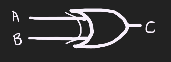
A and B are inputs. Y is the output. The XOR symbol is the OR symbol with an extra curved line at the input side. (You can add an image of it here.)
Boolean expression
Y = A ⊕ B = A'B + AB'
The ⊕ means XOR. The long form says: the output is 1 when A is 0 and B is 1, or when A is 1 and B is 0.
Truth table (2 inputs)
| A | B | Y = A ⊕ B |
|---|---|---|
| 0 | 0 | 0 |
| 0 | 1 | 1 |
| 1 | 0 | 1 |
| 1 | 1 | 0 |
Compare this with the OR gate. The only row that changes is the last one OR gives 1, XOR gives 0.
XOR with more inputs
XOR ICs have only 2 inputs. To get more inputs, we chain gates: A ⊕ B ⊕ C means (A ⊕ B) ⊕ C. The result is 1 when an odd number of inputs are 1. This is called odd parity.
| A | B | C | Y = A ⊕ B ⊕ C |
|---|---|---|---|
| 0 | 0 | 0 | 0 |
| 0 | 0 | 1 | 1 |
| 0 | 1 | 0 | 1 |
| 0 | 1 | 1 | 0 |
| 1 | 0 | 0 | 1 |
| 1 | 0 | 1 | 0 |
| 1 | 1 | 0 | 0 |
| 1 | 1 | 1 | 1 |
Look at each row and count the 1s. The output is 1 when the count is 1 or 3, which are odd numbers.
Boolean laws for XOR
| Law | Expression |
|---|---|
| With 0 | A ⊕ 0 = A |
| With 1 | A ⊕ 1 = A’ |
| Same input | A ⊕ A = 0 |
| With complement | A ⊕ A’ = 1 |
| Commutative | A ⊕ B = B ⊕ A |
| Associative | (A ⊕ B) ⊕ C = A ⊕ (B ⊕ C) |
A' means NOT A. The second law is very useful that is XOR with 1 flips a bit, and XOR with 0 keeps it.
Building an XOR gate from other gates
Unlike AND, OR and NOT, an XOR gate has no simple one-transistor circuit. We usually build it from other gates instead.
From AND, OR and NOT:
Y = (A + B) · (A · B)'
This says A OR B must be true, but A AND B must not both be true.
From 4 NAND gates:
- N1 = (A · B)’
- N2 = (A · N1)’
- N3 = (B · N1)’
- Y = (N2 · N3)’
Because NAND is a universal gate, this circuit gives an exact XOR using only one type of gate.
XOR Gate Lab
We will be needing:
- Breadboard
- 7486 IC
- 5 V power supply
- 1 LED
- 1 resistor (220 Ω works well, anything up to 1 kΩ is fine)
- Jumper wires
We are using the 7486.
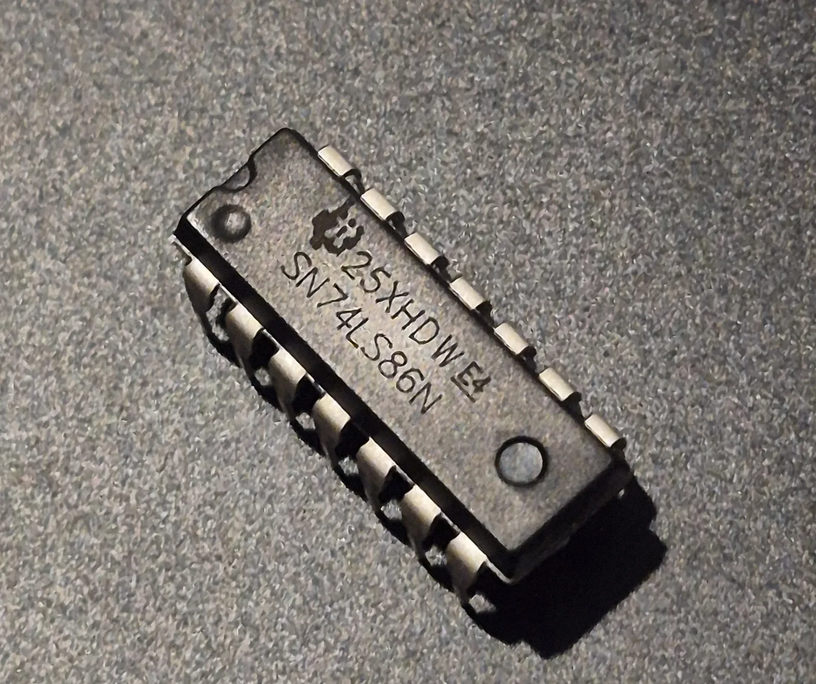
It has four separate 2-input XOR gates inside one chip, but we will use only the first one.
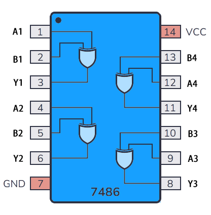
For the first gate, pins 1 and 2 are the inputs and pin 3 is the output. The other gates work the same way:
| Gate | Inputs | Output |
|---|---|---|
| 1 | Pins 1, 2 | Pin 3 |
| 2 | Pins 4, 5 | Pin 6 |
| 3 | Pins 9, 10 | Pin 8 |
| 4 | Pins 12, 13 | Pin 11 |
Place the chip across the middle gap of the breadboard so the two rows of pins do not touch each other. The notch on the chip marks the top. Pin 1 is on the left side of the notch. We connect pin 14 to the HIGH supply (+5 V) and pin 7 to ground.
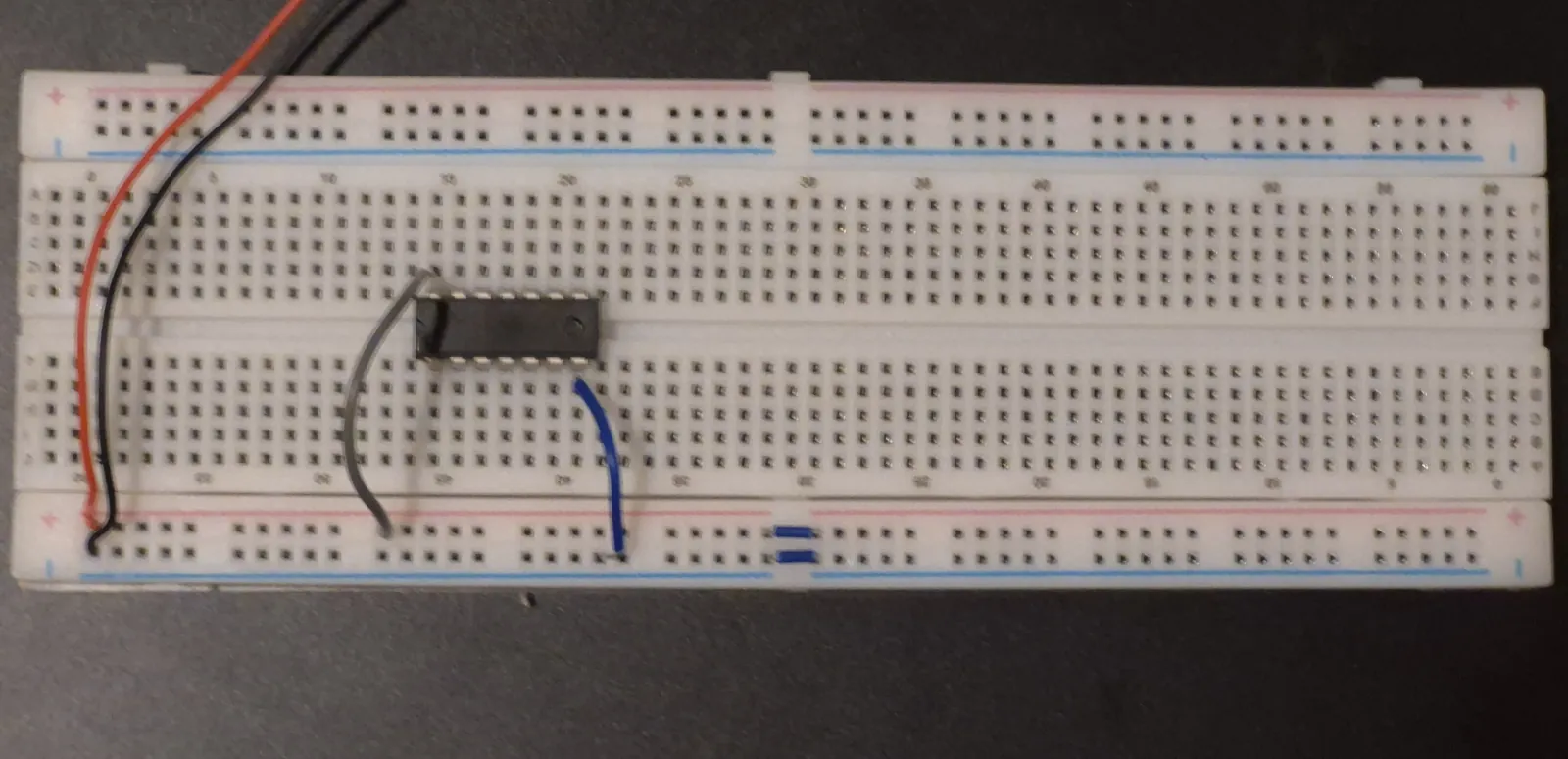
We connect one wire from the HIGH supply to pin 1 and another from the HIGH supply to pin 2. A wire connected to HIGH means that input is 1.
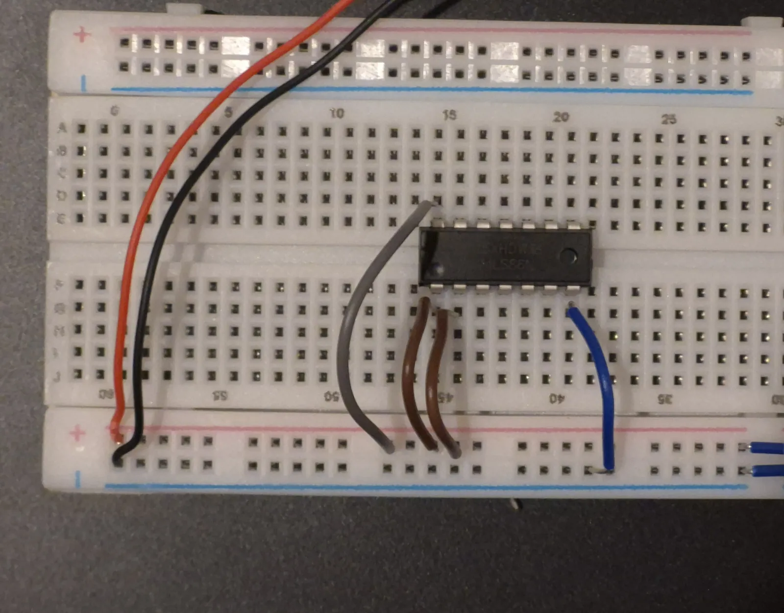
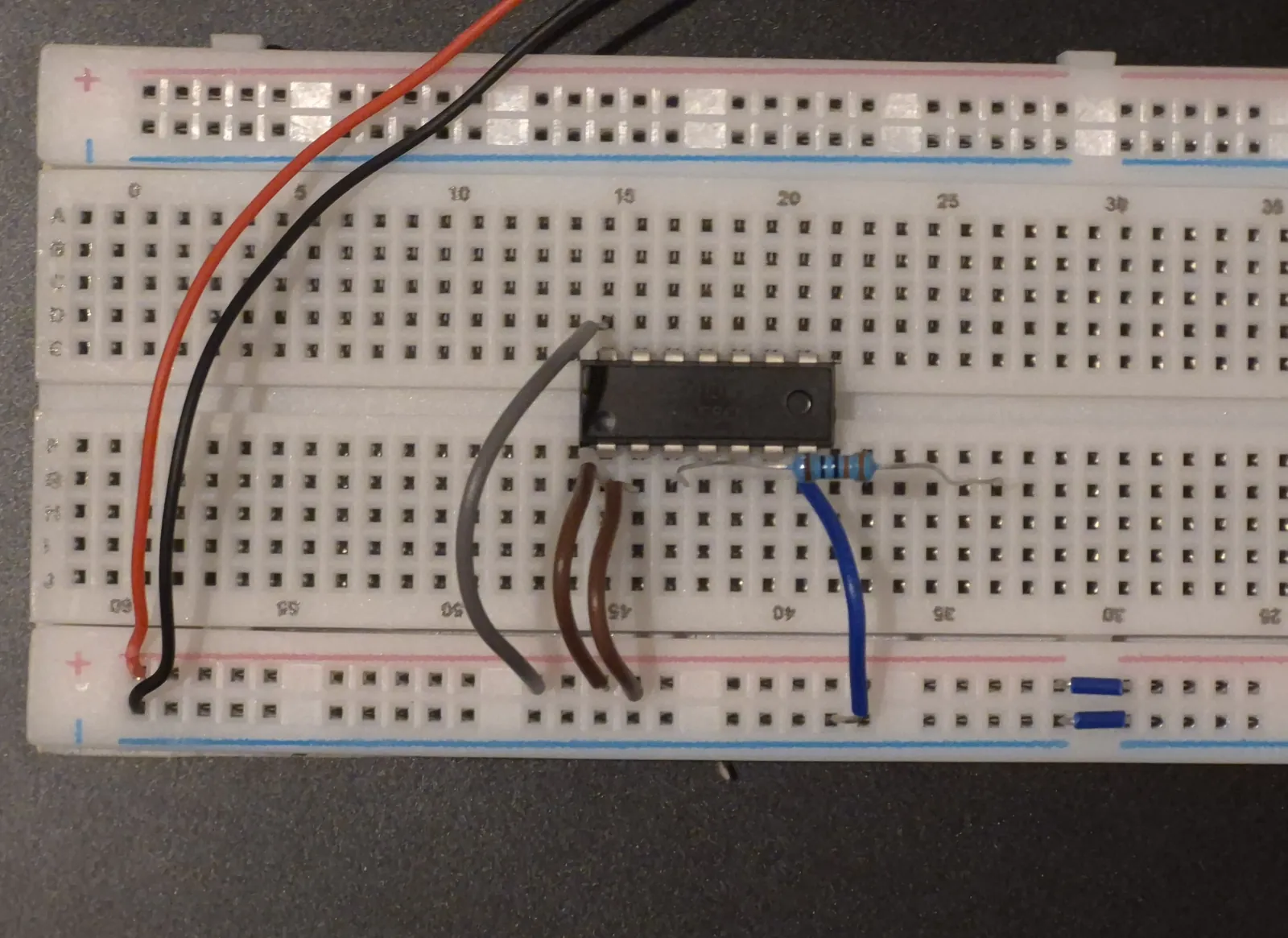
Pin 3 is our output. We cannot connect the LED directly to pin 3 because too much current can flow and burn it.
- Connect one leg of the resistor to pin 3.
- Put the other leg of the resistor in any free column on the breadboard. Any column works, as long as nothing else is in it. Holes in the same column are connected together.
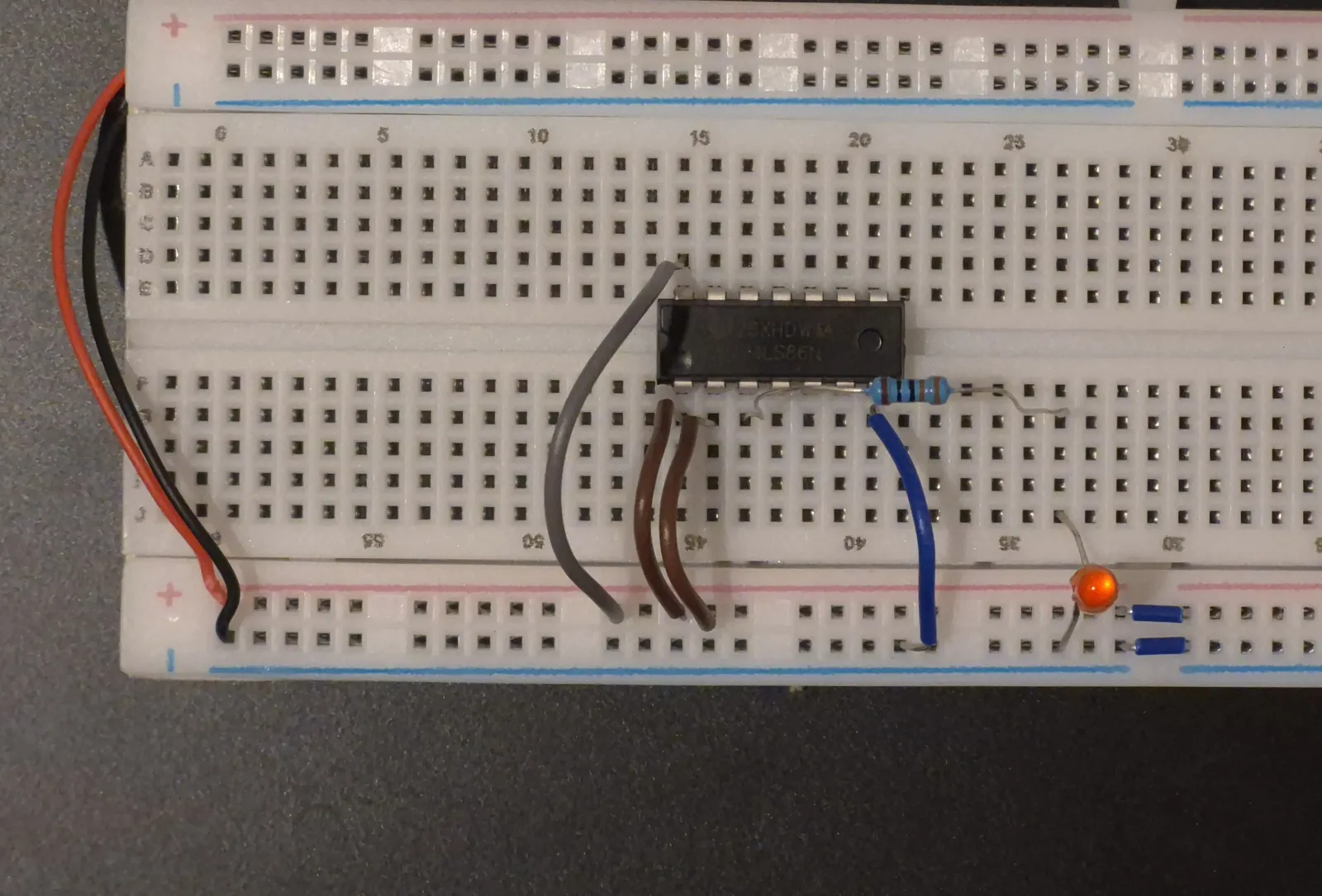
- In that same column, place the longer leg of the LED.
- Connect the shorter leg of the LED to ground.
Lets now test the truth table!
| Input 1 | Input 2 | LED | Output |
|---|---|---|---|
| HIGH | HIGH | OFF | 0 |
| HIGH | LOW | ON | 1 |
| LOW | HIGH | ON | 1 |
| LOW | LOW | OFF | 0 |
- Both wires are on HIGH. The LED is OFF, because the inputs are the same.
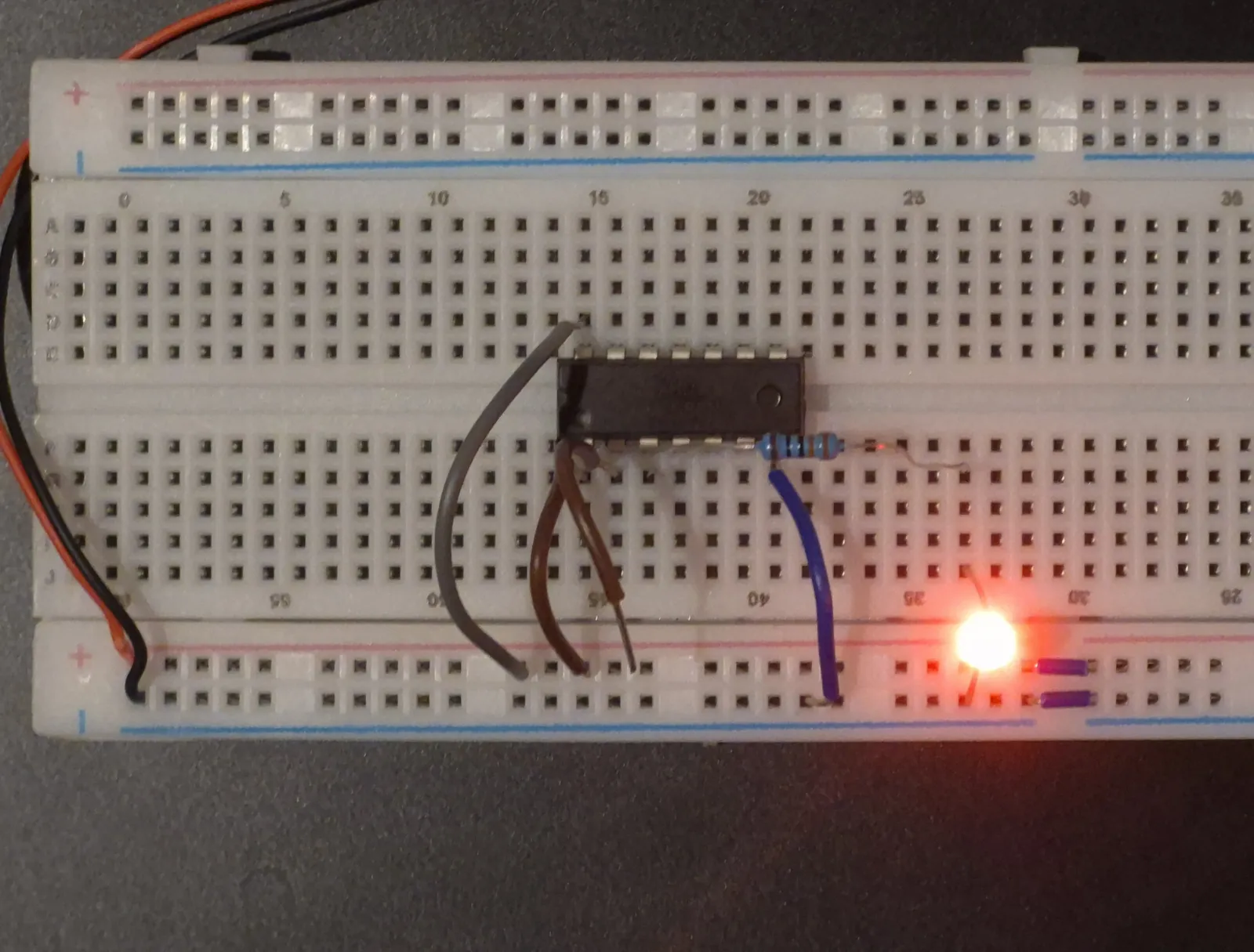
- Move input wire 2 from HIGH to ground. The LED turns ON, because the inputs are now different.
- Put wire 2 back on HIGH. The LED turns OFF again.
- Now move input wire 1 from HIGH to ground. The LED turns ON again.
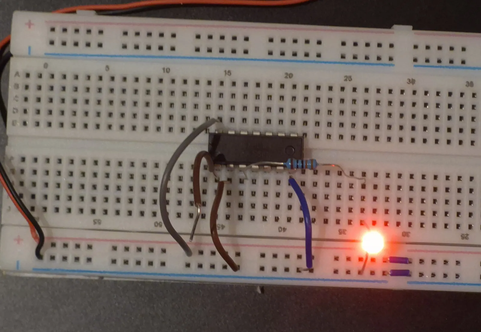
- Move both wires to ground. The LED turns OFF, because the inputs are the same again.
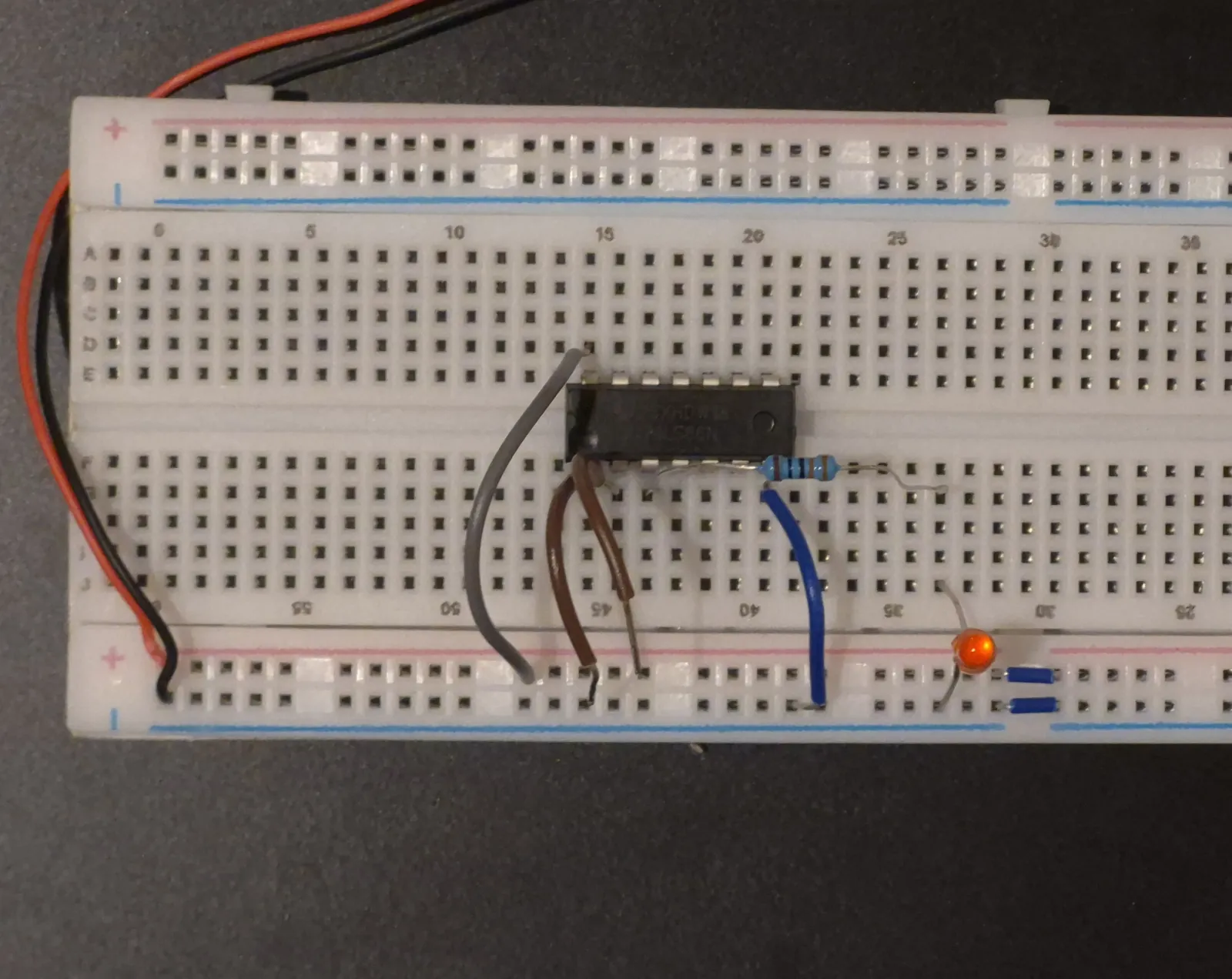
This shows that for an XOR gate, the output is HIGH only when the inputs are different. This is the difference from the OR gate: with both inputs HIGH, the OR gate lights the LED but the XOR gate does not.
Tip: Connect a LOW input to ground instead of just removing the wire. A wire connected to nothing is called a floating input, and on TTL chips like the 7486 it can act like HIGH. If you only remove the wire, the LED will not turn ON and you will think the gate is broken.